
Slip of AC Induction Motors and How To Minimize It
By Mauri Peltola, ABB Oy, Drives
The AC induction motor is often referred to as the workhorse of the industry. This is because it offers users simple, rugged construction, easy maintenance and cost-effective pricing. These factors have promoted standardization and development of a manufacturing infrastructure that has led to a vast installed base of motors; more than 90 per cent of all motors used in industry worldwide are AC induction motors.
In spite of this popularity, the AC induction motor has two basic limitations:
- the standard motor is not a true constant-speed machine; and
- is not inherently capable of providing variable-speed operation.
Both of these limitations require consideration, as the quality and accuracy requirements of motor/drive applications continue to increase.
This article explains the reason for the first limitation – slip -- and ways to minimize it. And, the best methods to control motor speed with power electronics now available are detailed, including technology to minimize the negative effects of slip.
Motor Slip is Necessary for Torque Generation
An AC induction motor consists of two basic assemblies – stator and rotor. The stator structure is composed of steel laminations shaped to form poles. Copper wire coils are wound around these poles. These primary windings are connected to a voltage source to produce a rotating magnetic field. Three-phase motors with windings spaced 120 electrical degrees apart are standard for industrial, commercial and residential use.
The rotor is another assembly made of laminations over a steel shaft core. Radial slots around the laminations' periphery house rotor bars – cast-aluminium or copper conductors shorted at the ends and positioned parallel to the shaft. Arrangement of the rotor bars looks like a squirrel cage; hence, the well-known term, squirrel-cage induction motor. The name "induction motor" comes from the alternating current (AC) "induced" into the rotor via the rotating magnetic flux produced in the stator.
Motor torque is developed from the interaction of currents flowing in the rotor bars and the stators' rotating magnetic field. In actual operation, rotor speed always lags the magnetic field's speed, allowing the rotor bars to cut magnetic lines of force and produce useful torque. This speed difference is called slip speed. Slip also increases with load and it is necessary for producing of torque.
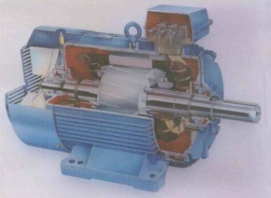
Figure 1. Squirrel cage ac induction motor opened to show the stator and rotor construction, the shaft with bearings, and the cooling fan.
Slip Depends on Motor Parameters
According to the formal definition, the slip (s) of an induction motor is:
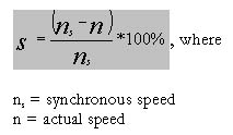
For small values of motor slip, the slip (s) is proportional to the rotor resistance, stator voltage frequency, and load torque -- and is in inverse proportion to the second power of supply voltage. The traditional way to control the speed of a wound rotor induction motor is to increase the slip by adding resistance in the rotor circuit. The slip of low-horsepower motors is higher than those of high-horsepower motors because of higher rotor winding resistance in smaller motors.
As seen in Table 1, smaller motors and lower-speed motors typically have higher relative slip. However, high-slip, large motors and low-slip, small motors also are available.
You can see that full-load slip varies from less than one percent (in high-HP motors) to more than five percent (in fractional-HP motors). These variations may cause load-sharing problems when motors of different sizes are mechanically connected. At low load, the sharing is about correct, but at full load, the motor with lower slip takes a higher share of the load than the motor with higher slip.
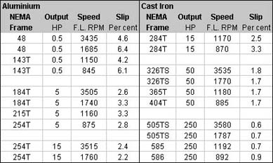
Table 1. Motor slip of selected aluminium and cast iron NEMA motors, with synchronous speed ranging from 3600 RPM to 900 RPM.
As shown in Figure 2, the rotor speed decreases in proportion to the load torque. This means that the rotor slip increases in the same proportion.
Figure 2. The speed curve of an induction motor. The slip is the difference in rotor speed relative to that of the synchronous speed. CD = AD – BD = AB.
Relatively high rotor impedance is required for good across-the-line (full voltage) starting performance (meaning high torque against low current), and low rotor impedance is necessary for low full-load speed slip and high operating efficiency. The curves in Figure 3 show how higher rotor impedance in motor B reduces the starting current and increases the starting torque -- but it causes a higher slip than in standard motor A.
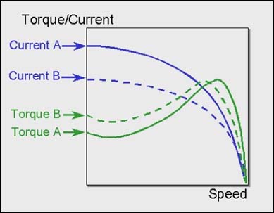
Figure 3. Torque/speed and current/speed curves for a standard motor A (full lines) and a high-torque motor B (dotted lines).
Methods to Reduce Slip – Motor Choice, Oversizing
The use of synchronous motors, reluctance motors or permanent-magnet motors can solve the problem of slip, because there is no measurable slip in these three types of motors. Synchronous motors are used for very high-power and very low-power applications, but to a lesser extent in the medium-horsepower range, where many typical industrial applications are. Reluctance motors also are used, but their output/weight ratio is not very good and, therefore, they are less competitive than the squirrel-cage induction motors.
A potential growth market is for permanent magnet (PM) motors -- used with electronic adjustable speed drives (ASDs). The main benefits are: accurate speed control without slip; high efficiency with low rotor losses; and the flexibility of choosing a very low base speed (eliminating the need for gear boxes). The use of PM motors is still limited to certain special applications, mainly because of high cost and the lack of standardization.
Selecting an oversized AC induction motor is a second way to reduce slip. Why? -- larger motors typically have a smaller quantity of slip, and slip gets smaller with a partial (rather than full) motor load.
Example: Refer to Table 1. The required power is 10 HP at about 1,800 rpm and 1.5 percent speed accuracy is required. We know that a 10 HP motor has a slip of 4.4 percent. Can we achieve an accuracy of 1.5 percent with a 15 HP motor? Answer: The full-load slip of the 15 HP motor is 2.2 percent, but the load is only 10/15 = 0.67. The slip will be 67 percent of 2.2 and equals 1.47 percent, which fulfils the set requirements. The disadvantages with over sizing are: with the larger motors, there's higher energy consumption, increasing investment and operation costs.
Adjustable Speed AC Drive is Often the Best Solution
The inherent limitations of the AC induction motor mentioned at the beginning of this article -- no constant speed and no speed control -- can be solved through use of adjustable speed control (ASDs). The most common AC drives today are based on pulse-width modulation (PWM). The constant AC line voltage with 60 or 50 cycles per second from the supply network is rectified, filtered, and then converted to a variable voltage and variable frequency. When this output from the frequency converter is connected to an AC motor, it is possible to adjust the motor speed.
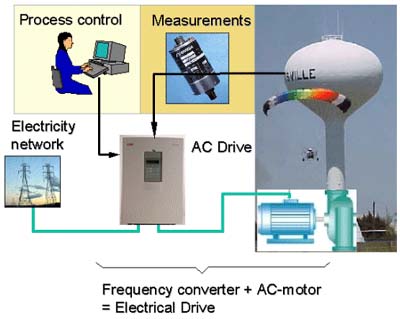
Figure 4. A simple control system with an AC drive: controlling the speed of the pump controls the water level in a water tower.
When using an AC drive for adjusting the motor speed, there are many applications where motor slip is no problem anymore. The speed of the motor is not the primary control parameter; rather, it could be the liquid level (as in Fig. 4), air pressure, gas temperature -- or something else. There are still many drive applications where high static speed accuracy and/or dynamic speed accuracy are required. Such applications are printing machines, extruders, paper machines, cranes, elevators, etc.
There also are many machines and conveyors where speed control between sections driven by separate motors have to be synchronized. Instead of over sizing the motors to eliminate the speed error caused by slip, it can be better to use sectional drive line-ups with separate inverters for each single motor. The inverters are connected to a DC-voltage bus bar supplied by a common rectifier. This is a very energy-efficient solution, because the driving sections of the machinery can utilize the braking energy from decelerating sections (regeneration).
Slip compensation can be added to AC drives, to reduce the effect of motor slip. A load torque signal is added to the speed controller to increase the output frequency in proportion to the load. Slip compensation cannot be 100 per cent of the slip because of rotor temperature variations that may cause over-compensation and unstable control. But the compensation can achieve accuracies up to 80 per cent, meaning slip can be reduced from 2.4 per cent to about 0.5 per cent.
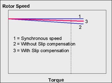
Figure 5. The effect of the slip compensation.
Vector and Direct Torque Control Improve Speed Control
The newest high performance technologies in the field of adjustable speed drives are vector control and direct torque control, DTC™. Both of these use some kind of motor model and suitable control algorithms to control the motor torque and flux, instead of the voltage and frequency parameters used in PWM drives. The difference between the traditional vector control and DTC is that DTC has no fixed switching pattern for each voltage cycle. DTC, a technology proprietary to ABB, switches, instead, the inverter according to the load needs, calculated/adjusted 40,000 times per second. This makes DTC especially fast during instant load changes and minimizes the need/effect of dramatic speed changes, once the load/process is in operation.
What is Direct Torque Control, DTC?
DTC is an optimized AC drives control principle, in which inverter switching directly controls the flux and torque variable of a motor/load.
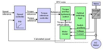
Figure 6. Block diagram of Direct Torque Control, DTC.
The measured input values to DTC control are motor current and DC link and voltage. The voltage is defined from the DC-bus voltage and inverter switch positions. The voltage and current signals are inputs to an accurate motor model, which produces an exact actual value of stator flux and torque every 25 microseconds.
Two-level motor torque and flux comparators compare the actual values to the reference values produced by torque and flux reference controllers. The outputs from these two-level controllers are updated every 25 microseconds and they indicate whether the torque or flux has to be changed or not.
Depending on the outputs from the two-level controllers, the switching logic directly determines the optimal inverter switch positions. This means that every single voltage pulse is determined separately at "atomic level." The inverter switch positions again determine the motor voltage and current, which, in turn, influence the motor torque and flux (because this control loop is closed, the need for encoders is eliminated in most applications).
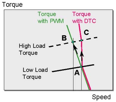
Figure 7. Comparison between PWM modulation and DTC drive control during load impact: A to B with PWM control and A to C with DTC control.
The reason why DTC control reacts faster than PWM control is shown in Fig. 7. The motor is running with low load at point A and the load has a stepwise increase to high load. The higher torque with the PWM control is achieved by reduced speed from A to B. This is quite a slow procedure. The higher torque with the DTC control is achieved by direct increase of torque from A to C and this procedure is about ten times (10x) faster than that of PWM control.
Slip compensation with DTC is instant and it creates an accuracy, which is typically 10 per cent of the nominal motor slip. That means speed accuracy of 0.1 to 0.5 per cent. This enables the use of DTC drives in many applications where previously a tachometer-based vector control was needed. For applications demanding even higher accuracy, it is possible to add a pulse encoder to a DTC drive.
Contact the author at: Mauri.Peltola@fi.abb.com
For more information on ABB Drives & Power Electronics, contact: Becky Nethery, Manager, Marketing Communications, ABB Inc., Automation Technology Products Division, Drives & Power Electronics, 16250 West Glendale Drive New Berlin, WI 53151-2840, Tel: (262) 785-8363, Fax: (262) 780-5120, e-mail: becky.nethery@us.abb.com, http://www.abb-drives.com