
Ground Rules by John Cadick: The Equipment is in Service - Now What?
Ground System Inspection
By John Cadick, P.E., Cadick Corporation
Introduction
Grounding systems provide the "basis" upon which our electrical system is founded. They provide variety of services including safer operating conditions, minimized surge voltages, operational protective schemes, and additional voltage availability.
What is a grounded power system? It is, simply, a power system in which one or more wires are connected to the earth or some electrical conductor that takes the place of the earth. Virtually all modern 120 volt systems, both household and industrial, are grounded systems. Most are of the "three wire" variety with one hot wire, one neutral wire, and one ground wire. Larger three-phase systems are usually grounded, and consist of three hot wires and one ground wire, and one grounded neutral wire.
This article will briefly discuss the characteristics of grounded systems, starting with 120-volt systems and then discussing higher voltages. The most important material is the discussion of the electrical and mechanical checks that are performed on grounding systems to make sure that they are operating properly.
Systems 120 volts and below
120 volt power, commonly called "household current", is by far the most commonly used source of electrical power – at least in the United States. 120 Volts is also responsible for more deaths and injuries than any other voltage simply because there is so much of it. Normally terminating in a recep-tacle, such systems were ungrounded for many years. Starting sometime in the late 1940s or early 1950s a third "ground" wire was added to the 120-volt circuits. The ground in the receptacle must, of course, be connected to a ground wire at the lighting panel from which it gets its power. (See article 250 of the National Electric Code for details on grounding of such systems.) Several manufacturers make a small plug in device that can be plugged into the receptacle with a suspicious ground. This devices has a set of indicator lights on the front. Abnormalities on the circuit into which the device is plugged, (e.g. reversed ground and neutral, improper ground, or open ground) will cause the lights on the test device to illuminate in a distinctive pattern. In addition to this test, a visual inspection should be performed to insure that the ground is properly connected.
Some 120-volt equipment is called "double insulated" and has no ground connector in its plug. Such a tool needs no ground since it has a double insulation system.
Both three wire systems and two wire (double-insulated) systems may be protected with a Ground Fault Circuit Interrupter (GFCI). (Figure 1) These devices can be built into the receptacle, a panel board circuit breaker, or can be plugged into a grounded receptacle. When the GFCI senses more than 5 milliamperes difference between the "hot" lead current and the neutral lead, it trips and all power is cut off to the faulty circuit. Five milliamps is barely above the threshold of perception for most human beings and is generally not harmful; however, you should realize that the ground fault interrupter does not limit the fault current to that value. It merely trips very quickly.
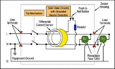
GFCIs have the advantage of being easy to test. Just push the "test" button on the GFCI and all of the circuitry and switching is tested. This should be done at least every six months to all GFCI circuits.
Grounding systems and earth connections for voltages over 120 volts
The grounding system for the higher voltage circuits is normally composed of multiple ground rods (called earth electrodes) which are all bonded to one of the supply systems wires, each other, and to the frame of all system equipment. In addition, the grounding electrodes may be bonded to a buried network of bare copper wire called a ground grid. A complete discussion of such grounding systems is beyond the scope of this course; however, the test and inspection of the major grounding system is critical to efficient and safe power system operation.
Visual and mechanical inspection
- Inspect the ground system for compliance with drawings. In particular observe the following:
- Are the ground rods in the right location.
- Are the ground rods the right size.
- Are all grounding conductors properly bonded together.
- Are all equipment frames properly bonded to the ground system.
- Are all ground rods bonded properly to the ground grid if it exists. (The ground grid is a grid of wires bonded together and buried immediately below the surface of the earth. Such grids serve to keep all frames in the system at the same voltage with respect to ground. They also help to keep the overall ground re-sistance at a low value.)
- Are the ground rods in the right location.
- Perform three (3) point fall-of-potential test per IEEE Standard 81, Section 9.04 on the main grounding electrode of the system. (Figure 2)
- Perform the two (2) point method test per IEEE No. 81, Section 9.03 to determine the ground resistance between the main grounding system and all major electrical equipment frames, system neutral, and/or derived neutral points.
or
Perform ground continuity test between main ground system and equipment frame, system neutral, and/or derived neutral point. This test shall be made by passing a minimum of one (1) Ampere dc current between ground reference system and the ground point to be tested. Voltage drop shall be measured and resistance calculated by the voltage drop method.
- The main ground electrode system resistance to ground should be no greater than five (5) ohms for commercial or industrial systems and one (1) ohm or less for generating or transmission stations grounds unless otherwise specified by engineering design.
Figure 2 shows the connections and voltage profile for the fall of potential method of meas-uring ground resistance. The test set (a ground resistance ohmmeter) injects an alternating current between the rod (or system) and the current electrode (C). The distance (D) may vary however it should never be less than approximately 100 feet and ideally should be a distance of five (5) times the longest dimension of the station grid.
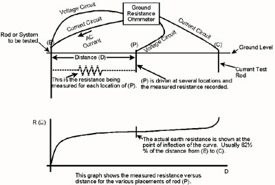
The potential electrode (P) is driven at various points between the station grid and the current electrode and the potential is measured. The ground resistance ohmmeter then calculates the resistance between the rod (P) and the rod under test (E). The resistance at each point is calculated by dividing the measured potential by the injected current. The bottom part of Figure 1 shows the curve that will result when re-sistance is plotted again distance (X). The inflection point (I) is the actual ground system value. This point usually occurs at a point approximately 62 % from the ground grid to the current electrode. If the curve does not resemble the shape shown in Figure 2, the current electrode is probably not far enough from the ground grid. For a more complete explanation of ground resistance measurement fundamentals go to the AEMC website. There you can download the technical paper entitled Understanding Ground Resistance Testing. This excellent paper explains ground resistance and ground resistance measurement in great detail.
A registered professional engineer, John Cadick has specialized for three decades in electrical engineering, training, and management. In 1986 he created Cadick Professional Services (forerunner to the present-day Cadick Corporation), a consulting firm in Garland, Texas. His firm specializes in electrical engineering and training, working extensively in the areas of power system design and engineering studies, condition based maintenance programs, and electrical safety. Prior to the creation of Cadick Corporation, John held a number of technical and managerial positions with electric utilities, electrical testing firms, and consulting firms. Mr. Cadick is a widely published author of numerous articles and technical papers. He is the author of the Electrical Safety Handbook as well as Cables and Wiring. His expertise in electrical engineering as well as electrical maintenance and testing coupled with his extensive experience in the electrical power industry makes Mr. Cadick a highly respected and sought after consultant in the industry. (Back to top)