Ground Rules by John Cadick: Power System Studies (Part 3 of 3)
By John Cadick, P.E., Cadick Corporation 
This week I will finish the short survey of Power System studies as defined in ANSI/IEEE Standard Std 399.
Reliability
As defined by the IEEE standards, reliability is expressed as the frequency of interruptions and expected number of hours of interruption during one year of system operation. The development of a system reliability study involves calculation of indexes (system reliability indexes) of various types. A reliability index is the probability that a device will function without failure over a specified time period. System modifications and designs may be "what iffed" to evaluate their effect on system reliability indexes.
The subject of reliability is complex enough to have warranted an entire standard dedicated to it. ANSI/IEEE Standard Std-493 (The Gold Book) is a must have for anyone performing or considering a reliability analysis.
With the increasing emphasis on costs of outages, system reliability has become a key issue for both utilities and industrial facilities. A reliability analysis provides quantitative data that can be used to analyze, and if necessary justify, the decisions made during system operation and design. The probability methods used are proven techniques and the results are defensible.
Ground Mat Analysis
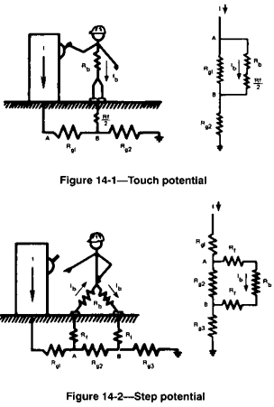
With normal current flows, the voltage differences between the various non-current carrying conductors and the earth will be small. Thus, someone touching a grounded piece of metal while standing on the ground will experience a very small voltage from hand to feet (touch voltage). Someone walking across a substation yard will experience very little voltage between the feet (step voltage.) See Figures 14-1 and 14-2 for illustrations of step and touch potential. Note that these illustrations are taken from ANSI/IEEE Std 399-1997.

During a short circuit however, the current flow through the earth can create a substantial voltage drop. Thus, as can be seen from Figures 14-1 and 14-2, a substantial, possibly lethal, voltage drop can be induced across the body.
A ground grid provides a very low current path for the fault current. Thus the worker is protected from lethal voltages since the voltage drop across the grid is so small. A ground grid must be properly installed to obtain maximum effectiveness. The goal of a ground grid study is to identify the proper design for the grid (wire size, grid size, etc) and the location of ground rods. Such a study results in the optimum design and, therefore, minimum step and touch voltages.
Harmonic analysis (Power Quality)
Modern power systems are sometimes plagued by the presence of waveform distortion. Waveform distortion is introduced by a variety of types of loads including solid state power supplies, inverters, fluorescent lighting, and other such equipment. Waveform distortion can causes a variety of system problems including
- Control/computer system interference
- Watt-hour meter errors
- Heating of rotating machinery
- Overheating/failure of capacitors
These same computer programs can then be used to model corrective actions such as installation of filters, isolation transformers, and other such items. The harmonic analysis can use the same system model that is developed for many of the other studies such as the short circuit study, coordination study, load flow, and motor starting study. The only thing that usually needs to be added are the models of the various harmonic sources. Most harmonic analysis computer programs have standards models in their libraries.
DC supply systems
This newest addition to the standard studies is performed to help insure that the DC power system is adequate. Std 399 defines five critical elements including:
- System modeling. Sources, branches, and loads.
- Load flow/voltage drop. During battery discharge and motor starting
- Short-circuit. Peak, time constant, rate of rise, and steady-state.
- Battery sizing.
- Charger sizing.
Conclusion
These last three columns have barely scratched the surface of these topics. A modern power system should be properly engineered by performing all of these studies and updating them on a regular basis. A good start on this studies is the purchase of the IEEE color book series, especially the Red, Buff, Brown, Gold, and Bronze books.
A registered professional engineer, John Cadick has specialized for three decades in electrical engineering, training, and management. In 1986 he created Cadick Professional Services (forerunner to the present-day Cadick Corporation), a consulting firm in Garland, Texas. His firm specializes in electrical engineering and training, working extensively in the areas of power system design and engineering studies, condition based maintenance programs, and electrical safety. Prior to the creation of Cadick Corporation, John held a number of technical and managerial positions with electric utilities, electrical testing firms, and consulting firms. Mr. Cadick is a widely published author of numerous articles and technical papers. He is the author of the Electrical Safety Handbook as well as Cables and Wiring. His expertise in electrical engineering as well as electrical maintenance and testing coupled with his extensive experience in the electrical power industry makes Mr. Cadick a highly respected and sought after consultant in the industry. (Back to top)
