Ground Rules by John Cadick: For You Relay Techs - Fault Voltages
 By John Cadick, P.E., Cadick Corporation
Last week and the week before I was teaching a protective relay maintenance course to a group of substa-tion technicians. While covering distance relays, a number of questions arose about the voltage vectors that a relay will see during a short circuit. Along with this came the question as to what kind of voltage and current phase angles have to be applied to test the relay. This week I will answer three questions that arose during that class:
- What is "phase angle?"
- What do the voltages at the relay look like during a three phase and a phase-to-phase short circuit?
- Why is there a 30 degree phase angle difference when I test a three phase distance relay such as the ABB KD relay?
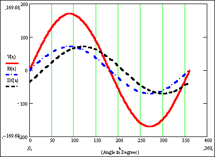
Figure 1 - Voltage (120 V RMS) & Current (50 Amperes RMS)
What is "phase angle?"
The voltages and the currents in a power system are sinusoidally alternating. This means (see Figure 1) that they start at zero, change to a maximum value, return to zero, change to a minimum value, and then return to zero. In an American power system, this total process occurs sixty (60) times each second. Consider the voltage [V(a)] (the red curve) shown in Figure 1. One alternation occurs in 1/60 of a second. If we divide that alternation into 360 equal parts, we refer to each part as a degree. Thus, one alternation includes 360 degrees.
I0(a) (the blue curve), is in phase with V(a). This is because I0(a) and V(a) hit zero, peak, and all in be-tween values at exactly the same time. I30(a), on the other hand, is lagging the other two by 30 degrees. This is because it hits its zero and peak values 1/12 of an alternation or 30 degrees after the others. We say that the phase angle between V(a) and I30(a) is –30 degrees.
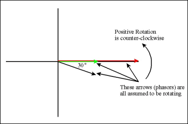
Figure 2 - Voltages and Currents from Figure 1 shown as phasors
Figure 2 shows the same idea except that we use arrows called "phasors" to represent the alternating voltages and currents. Thus we can show that magnitude and phase angle relationship between voltages and/or currents using this phasors.
What do the voltages at the relay look like during a three phase and a phase-to-phase short circuit?
Figure 3 shows a "normal" balanced set of three phase voltages. The length of each side of the tri-angle is the rms value of the voltage, for example 138,000 Volts. The phase relationship is such that there are 60 degrees between each phase.
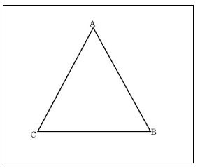
Figure 3 Balanced 3 phase voltages with no fault
Figure 4 is the same system with a three-phase short circuit. Notice that the voltages are all col-lapsed an equal amount. The reason for this is the high current flowing to the short circuit causes a voltage drop on the lines between the source and the relay. More voltage drop means less voltage at the relay. Since the three phases are affected equally, they all reduce by the same amount. Of course, a system is rarely this balanced; however, it is close enough to be used for testing relays.
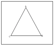
Figure 4 Voltage for a three-phase fault.
If a phase-to-phase fault occurs only two of the phases have high currents. This means that the voltage between those two phases will decrease. This condition is shown in Figure 5.
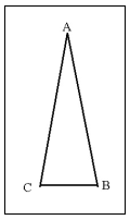
Figure 5 B to C phase fault voltages at relay.
Note that the B to C phase voltage has collapsed to a lower value while the A to C and A to B voltages are equal.
Why is there a 30 degree phase angle difference when I test a three phase distance relay such as the ABB KD relay?
At unity power factor, the phase to neutral currents are in phase with the phase to neutral voltages. For ex-ample IB will be in phase with VB at unity power factor. The phase current and the phase-to-phase voltage, on the other hand, will be different. At unity power factor, IB will lag VBC by 30 degrees.
In the "old" days, before modern test equipment made it possible to vary phase angles with ease, test set-ups often had to use phase-to-phase voltage as the reference against the fault current. When testing a KD, for example, VBC might be used as the reference for the phase angle measurement. Consider the two types of tests for such a relay, the three-phase test and the phase-to-phase test.
The three-phase test
Since IB lags VBC by 30 degrees to begin with, the fault angle will be added to the initial angle. Thus during a fault with a 75 degree characteristic (phase to neutral), IB will lag VBC by 30 degrees plus 75 degrees for a total of 105 degrees. This is why all of the three phase tests for a KD (and others) has to add 30 degrees to the test angle. Because the phase-to-phase voltage starts (pre-fault) at a 30 degree angle ahead of the current.
The phase-to-phase test
Things are slightly different for the phase-to-phase test. Consider Figure 6.
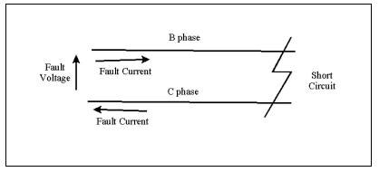
Figure 6. Phase-to-phase short circuit
In this condition, the fault current will lag the fault voltage by the characteristic angle e.g. 75 degrees. But note that the fault voltage is also the phase-to-phase voltage, in this case VBC. Note also that the fault current is IB. Clearly, the test current in this case will be set to 75 degrees. The 30 degree adder only applies to the three phase short circuit.
Questions? Comments? Send them to editor@electricnet.com.
A registered professional engineer, John Cadick has specialized for three decades in electrical engineering, training, and management. In 1986 he created Cadick Professional Services (forerunner to the present-day Cadick Corporation), a consulting firm in Garland, Texas. His firm specializes in electrical engineering and training, working extensively in the areas of power system design and engineering studies, condition based maintenance programs, and electrical safety. Prior to the creation of Cadick Corporation, John held a number of technical and managerial positions with electric utilities, electrical testing firms, and consulting firms. Mr. Cadick is a widely published author of numerous articles and technical papers. He is the author of the Electrical Safety Handbook as well as Cables and Wiring. His expertise in electrical engineering as well as electrical maintenance and testing coupled with his extensive experience in the electrical power industry makes Mr. Cadick a highly respected and sought after consultant in the industry. (Back to top)
