A Unique Method of Evaluating Battery Capacity via Battery Impedance Data
There seems to be two questions a battery user will ask: "What is the capacity of the battery now?" and "When will it need to be replaced?" All of the testing that occurs is to answer these two questions. Naturally, its much easier said than done, especially since there are many types of batteries used in back-up systems: lead-acid – flooded and VRLA in 2V cells up to 12V jars and NiCd batteries. The capacity ranges from less than 1Ah to 4000Ah and more, plus limitless configurations – multiple strings, environmental conditions, duty cycles, etc. How does one know if a particular battery will support the load when it is called upon? In order to properly ensure adequate back-up, especially in view of decreasing resources and increasing regulations, testing of DC power system batteries and rectifiers is essential even if difficult. To manage and determine the state of health of the wide-range of batteries, a multitude of tests is necessary. Testing can encompass no testing up through full load tests. Traditionally, the cost of battery testing has been based on the premise that it is a cost rather than an investment in reliable service and confidence that the load will be suspported.
Proper Backup
There are two main reasons to have proper backup:
- to ensure adequate backup for critical equipment such as oil priming pumps and financial data center information
- to prevent interruptions in revenue streams and to avoid customer angst as in telecommunications systems
In larger installations, such as Central Offices and UPS sites, batteries are frequently flooded lead-acid. However, with the need for more power in an existing space, VRLA batteries are frequently used. There are very definite advantages of each, e.g., flooded batteries can tolerate temperature swings better since there is more mass to absorb the heat than VRLA cells. VRLA cells have considerably smaller footprints than flooded batteries. In smaller installations, the time to perform various tests is not significantly less than for larger systems on a test time per cell basis. So what tests are required to determine a battery's state of health (per IEEE)?
- Visual inspection
- Pilot cell temperature
- Ambient temperature
- Float voltage and float current on each cell and the total string
- Specific gravity and level of the electrolyte, if applicable
- Internal ohmic test such as impedance
- Intercell connection resistance
- Periodic discharge tests, if desirable
Once the data are taken, what happens next? Do they go into a pile on the desk, get filed, a report gets written? If a report is written, who reads it? Does it go into a pile on the desk, get filed…? It is important the data conversion process takes place – data to information to knowledge to action. Only then can you be more confident that the battery will support the load.
Introduction to Impedance Testing
Research has shown that internal battery cell impedance increases with decreasing capacity due to age and discharge history. A cell in poor condition due to age, poor maintenance or poor site conditions exhibits a high internal cell impedance, which can be caused by plate sulphation due to low float voltage, weak top lead welds and/or corrosion, negative lug rot, etc. An abnormally low impedance may be due to paste lumps on the plates, which would also exhibit low float voltage. Other problems such as poor intercell and intertier connections can also be identified. Cells of different sizes and manufacturers exhibit different impedance readings, but cells of similar size, age and manufacturer should exhibit similar readings unless there is a problem. Impedance testing is used to identify the possible loss of cell capacity, poor intercell connections, and poor intracell connections while the battery is in full operation.
Capacity has an inverse relationship to impedance (impedance rises as capacity decreases). The battery impedance test is an on-line ac test that was developed by Commonwealth Edison and described in a paper presented in 1988. This test determines the condition of a cell by capacitively coupling a low-frequency current to the battery and measuring the small ac voltage drop across the battery terminals. This measured value is then divided by the ac current passing through the battery to get the battery impedance following Ohm's Law. The condition of an individual cell can be determined by comparing its impedance value with the average for the entire string or, if available, the string's trend over time.
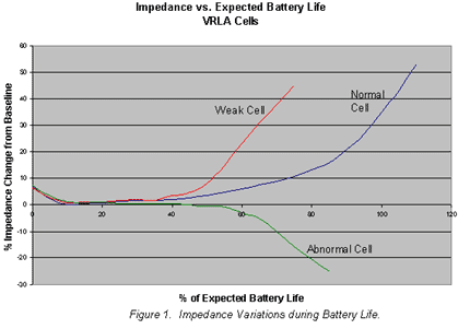
Trending impedance data highlights weak cells very quickly. Figure 1 shows the projected impedance variation over the lifetime of VRLA cells. Typically, a 35% increase in impedance of a VRLA cell correlates to about 80% battery capacity. (The initial impedance decrease is due to the improvement in battery capacity as it completes the formation process.) Based on high impedance readings, a decision can be made regarding: 1) perform more tests 2) give it an equalization charge (rarely) 3) jumper it out until a replacement can be obtained or 4) replace it on the spot assuming a replacement cell(s) is available. Obviously (3) is not realistic in 24V or 48V telecom installations.

Unlike load cycle testing that involves substantial downtime and repeated discharges, the impedance test requires no battery discharge. Test time is less than 30 seconds per cell and the battery does not have to be taken off-line.
Discharge Tests
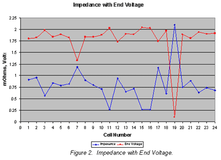
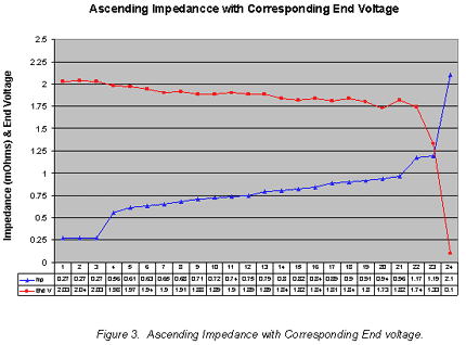
Discharge tests continue to be important tests. One way to enhance its usefulness is to perform an impedance test on the "as-found" battery immediately prior to performing the load test and a second impedance test after the battery has stabilized for about three days. See Figure 2 comparing "as-found" impedance with voltage at the end of a load test. A true correlation between battery capacity and impedance data can be obtained to enhance the ability of impedance data to predict battery condition. Figure 3 rearranges the data to show the correlation between impedance and capacity as a function of end voltage.


Data Interpretation
Whether a large or small battery is being tested, depending upon which test equipment is used, there are several methods to determine the state of health of each cell or jar in the string: instantaneous, short-term, and long-term. In all cases, it is beneficial to obtain baseline readings at battery commissioning.
The instantaneous determination of pass/warning/fail is compared to user-entered warning and fail values for resistance and a minimum voltage value. If the combination of resistance and voltage readings exceed the stored warning value, an LED will light and an audible alarm will sound. The same occurs in the "fail" mode.
Short-term analysis is performed on each cell or jar, but is based on the average for the entire string for that test. By comparing cells to each other a relative "weakness" is determined. The easiest way to see the comparison of each cell to the string is to plot the impedance in ascending order using a spreadsheet as shown in Figure 3. When a flooded cell has more than a 15% variation from the string average (>35% for VRLA), it should be investigated further.
Impedance readings can be used in the long-term to determine replacement criteria. Battery cell impedance values should be recorded and compared to previous readings to determine the cell's position on the curve of impedance versus cell life. Individual cell values varying by more than ± 40% from the initial baseline of the battery average typically indicate a problem with that cell (and ± 20% for flooded). A sample curve for VRLA batteries is shown in Figure 3 above. In order to facilitate the long-term interpretation of impedance values, AVO International maintains a database of impedance values of many battery types. For comparison purposes, this information is available upon request.
Intercell Connection Resistance
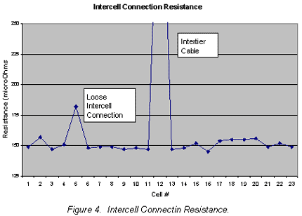
One of the most important tests that can be performed on a new battery before it is commissioned is a check of each and every intercell connector with a Digital Low Resistance Ohmmeter (DLRO) as shown in Figure 4. IEEE recommended practices specify that all intercell connection resistance values must be no more ten percent above of the lowest value. Now consider a typical intercell connection resistance in about 0.150 milliOhms allows for an increase of only 15 microOhms! Many times, the proper torquing of the intercell connectors is overlooked or in complex systems one intercell connector or bolt is most likely missed during the torquing process. Not uncommon also is a washer sticking to the No-Ox on the back of an intercell connector between the connector and the post. Experience has taught us that many battery failures have more to do with loose intercell connectors than actual cell failures.

Interruption in service can cause disaster to supported equipment. Consequently, a dependable backup power system is critical so when AC mains fail, costly service interruptions can be avoided. The power of good impedance data analysis makes you more confident in the battery.
